Saturday, February 27, 2021


 25th February 2021

 Further work on the machinery hall enclosure has now been done, almost bringing this phase to completion. The hall has now reached it full width of slightly more than 7 feet.
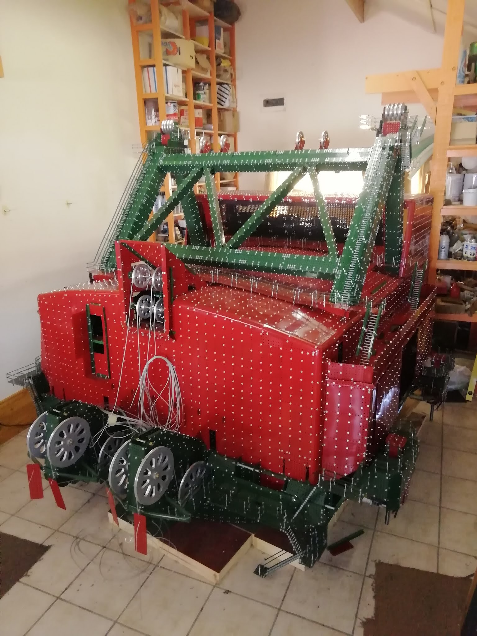
 

Fig. 78: Left frontal view (whole machine)

The side extension “lugs” on either side have been enclosed, as can be seen in figure 78, a view from the left front. A pair of stairways connect the left front roof to rooftop walkways which each cross over to the other side of the machine. The long stairway to the left gantry top leads off one side of the front walkway while a similar stairway to the right gantry top leads off the other side. At first I wondered why staff couldn’t just walk across the roof but then I pictured a wet or ice covered roof and I saw the reason! The purpose of the rear walkway seems to be to allow entry to the air filtration plant from either side and would also allow staff to clean insect build up from the front insect mesh using brushes on long poles.(My guess anyway.)


Fig. 79: Closer view of left front, showing removable side panels and stairways to the roof

Figure 79 is a closer view of the left hand side and shows the two short stairways in more detail. Also visible is some side panelling, in particular two removable panels measuring 18 by 15 inches. The space between them will be filled in by fixed plates when I am finished installing the rest of the machinery hall equipment. Still to come in this regard are the high powered hydraulic pumps which lift the whole machine on its walking feet and ersatz swing motors.

Fig. 80: Rear view of right hand hall extension. Note removable panels again
 

Figure 80 is a view of the right hand extension from the rear. The hole seen here will be filled by a door on hinges. I have seen pictures of Big Muskie with the door open and a cantilevered hoist beam extended outwards. I presume this is used to service the hydraulic pumps and other equipment out of reach of the main service crane. Also visible in figure 80 are two more removable panels. Note the asymmetry between left and right hand sides. As mentioned before this is because of the large cooling air plenum installed in the right side.

Fig. 81: View from rear showing air filtration plant in top floor


Figure 81 is a view from the rear showing the still open filtration plant. There are four large impellor compressors and each is mated to a boxcar sized microfilter unit. The two units on the right supply cooling air to the winding drum area and the two on the left likewise to the motor generator park which is visible below on the main hall floor. The main 5 foot service crane is visible between the two floors. A second, smaller crane rides on rails which traverse the filtration room. A small red plastic Meccano motor which powers the small crane can just be made out at the top of the picture. The crane has a cross traveller but it is not powered and neither is hoist due to space constraints and I have been unable to source small enough motors. The main crane has four wheels powered by a large 12V motor situated on the left side. Drive is taken across to the right by an 8mm shaft. A 4mm shaft would suffer from too much twist over such a long distance and the motion would be jerky as a result. The cross traveller on the large crane is powered by a small Meccano motor as is hoist.


Fig. 82: Front insect screen on air filtration plant

Figure 82 shows the insect screen painted black and sloped backwards at the front of the filtration plant. A similar screen will be installed at the rear.


Fig. 83: Later picture of rear with roof complete and four of six rear doors installed

By the time figure 83 was taken the last piece of roofing had been completed and the rear wall was well advanced with four of the six doors installed. Figure 84 shows these doors in the open position so as to allow the service crane to exit along with its load. Figure 85 shows a boxcar sized microfilter unit with staff safety rails around top.


Fig. 84: Rear doors opened

Fig. 85: A microfilter unit


Fig. 86: Main service crane rolled out the back on cantilever rails
 

Figure 86 shows the main service crane rolled out the opened rear doors on the cantilevered rail extensions. The two central wheels on either side are driven.

Wednesday, January 20, 2021


15th Jan 2021


The machinery hall enclosure has now been considerably advanced. All twelve of the main vertical stanchions and roof they support via six trusses have been installed (except for a short section of roof at the very rear). The twelve matching support stanchions the service crane rails are also in place and the rails themselves are nearly complete. Figure 70 shows a current overall view from the offside front. It shows a number of things apart from the front part of the roof. The second floor which houses the air filtration plant can be seen to the rear of the roof over the winding drum area. This view seems to show a translucent front to the area as the light from the garage window behind is visible through it. This is correct as this feature is meant to represent a fine mesh screen which prevented insects and birds from being drawn in by the air intakes on the prototype. I originally intended creating this screen out of  a fine galvanized fly screening but dropped the idea on learning that this product is  only available in nylon now at my hardware store. Instead I created the sense of permeability by reaming the 4.2mm holes in a series of 5 by 11 hole plates out to 8mm (all 55 except four in the corners). I know that this would not be effective against insects or even small birds if scaled up by a factor of 17, but  then like all Meccano it is only a representation of reality.

Fig. 70: Elevated frontal view  


Figure 71 is a view into the air filtration plant room from the rear, which is still open. The floor is supported by three trusses, the front one being a combination roof and floor truss to allow development of the curved roof into a flat floor. The rear truss is similar allowing the reverse transition while the central one is just a floor truss. Pictures of all these have been shown earlier. The insect screen is visible to the front and there will be a similar screen at the rear. Both screens have a slant to them which would prevent rain from being drawn in. At the far end of the picture an impellor type compressor can be seen. There will be four of these, each being mated to a large microfilter stack. I have no information on what these units looked like on the prototype but I did find the website of a company which specialises in building similar units for modern day draglines so I’ve had to extrapolate a bit!

Fig. 71: Inside the air filtration plant
  

At the top of the insect screen a strong roof support beam can be seen spanning the six foot wide from wall to wall distance. Attached to bottom of this beam is a five foot long rail on which a small service crane (about 22 inches wide) will run. The rail on the other side can just be seen in the top right of the figure.

Fig. 72: Close up of an impellor compressor (with ersatz motor in black)


Figure 72 is a close up of an impellor compressor unit with ersatz motor using a paint ca in black. The two compressors on the right supply cooling air to the front of the machine and they do this through a duct or plenum which is visible in figure 73 which shows the underfloor area of the filtration room. The silver plenum is created entirely out of recycled coffee tins as are the compressor/microfilters except for some laser cut quadrant plates seen in figure 72.

Fig:. 73:  Underside of filtration plant showing silver air supply plenum.
Fig. 74: Top of gantry, built from 2mm plate


Figure 74 shows the top section of the right of the gantry completed. It employs 2mm gauge plate as it has to support the forward pull of the boom system and the bucket (total weight about 200kg).

Fig. 75: Left hand gantry top showing aluminium pulleys of boom hoist mechanism


In figure 75 four 4inch diameter aluminium pulleys can be seen at the top of the left hand side of the gantry. These form part of the boom hoist mechanism. There will be similar pulleys at the top of the left hand minor boom and the whole device will be repeated on the right side.

Fig. 76:  Stairs to the top of gantry going up right front gantry stanchion.


Figure 76 shows a stairway from the roof up to the gantry top going up the right front gantry strut. There is a similar stairway on the left and the two are connected by a walkway going across the roof. The path to the roof will be from the top of the left lug addition to the hall which can be seen in figure 70. the walling of the two lugs will feature two large removable panels on either side, to see inside the finished hall.

Fig. Fig. 77:

Hall walling has now progressed to the rear. Figure 77 shows the right rear corner with the curved plate profile in red continuing that of the heavily built under frame in green. Also visible is the cantilevered extension to the service crane rail which will allow said crane to move out the back of the machine to drop its load on the ground (or the reverse). There will be a rather complicated set of six doors in the rear wall which will allow the crane plus whatever it is carrying to do this. Two doors open outward and four open inward. This is necessitated because of the double crank design of the back of the machine. Finally the two small holes seen in the walling are for the extractor fans from scrapped computers.