25th February 2021
Further work on the machinery hall enclosure has now been done, almost bringing this phase to completion. The hall has now reached it full width of slightly more than 7 feet.
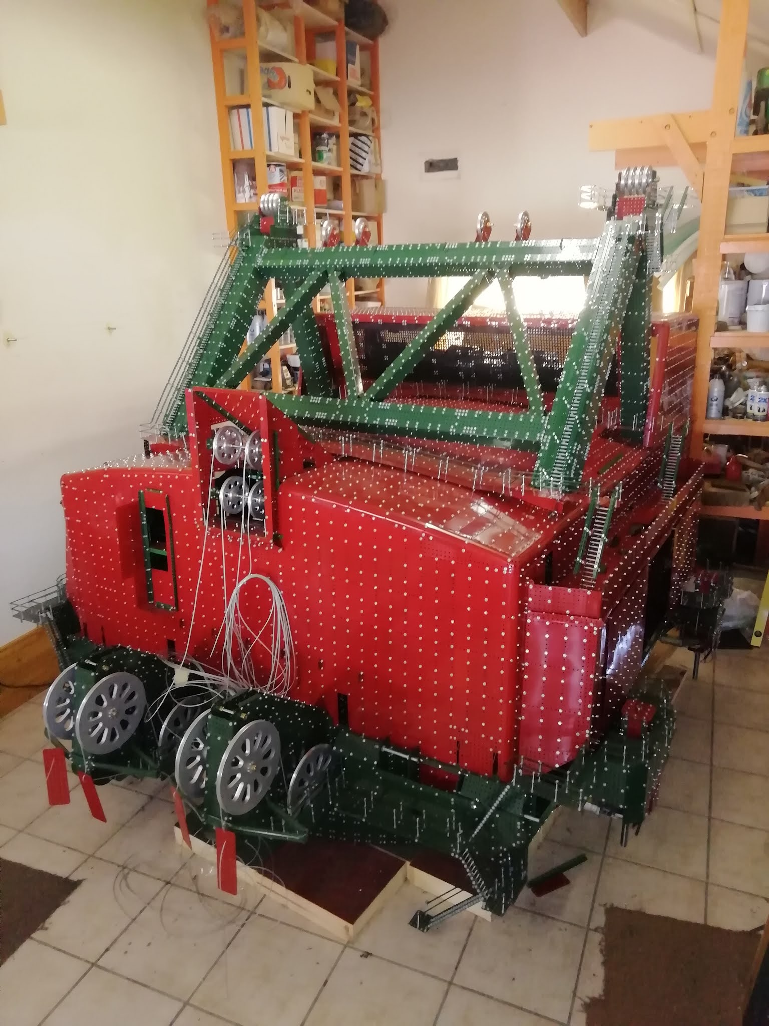
Fig. 78: Left frontal view (whole machine)
The side extension “lugs” on either side have been enclosed, as can be seen in figure 78, a view from the left front. A pair of stairways connect the left front roof to rooftop walkways which each cross over to the other side of the machine. The long stairway to the left gantry top leads off one side of the front walkway while a similar stairway to the right gantry top leads off the other side. At first I wondered why staff couldn’t just walk across the roof but then I pictured a wet or ice covered roof and I saw the reason! The purpose of the rear walkway seems to be to allow entry to the air filtration plant from either side and would also allow staff to clean insect build up from the front insect mesh using brushes on long poles.(My guess anyway.)

Fig. 79: Closer view of left front, showing removable side panels and stairways to the roof
Figure 79 is a closer view of the left hand side and shows the two short stairways in more detail. Also visible is some side panelling, in particular two removable panels measuring 18 by 15 inches. The space between them will be filled in by fixed plates when I am finished installing the rest of the machinery hall equipment. Still to come in this regard are the high powered hydraulic pumps which lift the whole machine on its walking feet and ersatz swing motors.

Figure 80 is a view of the right hand extension from the rear. The hole seen here will be filled by a door on hinges. I have seen pictures of Big Muskie with the door open and a cantilevered hoist beam extended outwards. I presume this is used to service the hydraulic pumps and other equipment out of reach of the main service crane. Also visible in figure 80 are two more removable panels. Note the asymmetry between left and right hand sides. As mentioned before this is because of the large cooling air plenum installed in the right side.

Fig. 81: View from rear showing air filtration plant in top floor
Figure 81 is a view from the rear showing the still open filtration plant. There are four large impellor compressors and each is mated to a boxcar sized microfilter unit. The two units on the right supply cooling air to the winding drum area and the two on the left likewise to the motor generator park which is visible below on the main hall floor. The main 5 foot service crane is visible between the two floors. A second, smaller crane rides on rails which traverse the filtration room. A small red plastic Meccano motor which powers the small crane can just be made out at the top of the picture. The crane has a cross traveller but it is not powered and neither is hoist due to space constraints and I have been unable to source small enough motors. The main crane has four wheels powered by a large 12V motor situated on the left side. Drive is taken across to the right by an 8mm shaft. A 4mm shaft would suffer from too much twist over such a long distance and the motion would be jerky as a result. The cross traveller on the large crane is powered by a small Meccano motor as is hoist.

Fig. 82: Front insect screen on air filtration plant
Figure 82 shows the insect screen painted black and sloped backwards at the front of the filtration plant. A similar screen will be installed at the rear.

Fig. 83: Later picture of rear with roof complete and four of six rear doors installed
By the time figure 83 was taken the last piece of roofing had been completed and the rear wall was well advanced with four of the six doors installed. Figure 84 shows these doors in the open position so as to allow the service crane to exit along with its load. Figure 85 shows a boxcar sized microfilter unit with staff safety rails around top.

Fig. 84: Rear doors opened
 | |||||
| Fig. 85: A microfilter unit |

Fig. 86: Main service crane rolled out the back on cantilever rails
Figure 86 shows the main service crane rolled out the opened rear doors on the cantilevered rail extensions. The two central wheels on either side are driven.