A work in progress
Following completion of my Bagger 288 model and Marion6360 Stripping Shovel in replica Meccano in 2016 I decided to build the Bucyrus Erie 4250-W Walking Dragline, also
knicknamed Big Muskie on account of the fact that it worked in the Muskingum
coal mine in Ohio, in a similar scale of 18 to 1.This is a scale I like to work
in as it allows modelling of many small details like hand rails and driver’s
cab furniture. One of the reasons I chose to build the 4250-W was that it was
the largest dragline ever built and I would be completing an unholy trinity of
the three largest fully mobile land based machines that ever were. ( My
threesome is completed by the Krupp built Bucket Wheel Excavator with machine
number 288 working for Rheinbraun coal in Germany.) The 288 model weighs in
at 1335kg, the Marion
at about 1250 kg while the B E 4250-W has a weight projected to come out at
1200kg. The ratios between these masses are about the same as those between prototype
masses. Incidentally this makes these models the largest such models in the
world by mass. To my mind mass seems to be the most sensible criterion for
making such a judgement. Using length, height or breadth leads inevitably to an
inconsistent criterion. Number of parts is a bit more reliable but not as
positive definitive as mass.
There were, however, other reasons for choosing Big Muskie .These were
bound up with the fact that many of the operating systems of a dragline were
very different from those of the
previous two diggers ( and digging has always been a part of my life even
though it has been hand digging out more cubic metres of earth and rock in
building the property I live on than I’ve had cooked breakfasts!) The method of
propulsion is completely different, in that the whole machine is lifted up on
two walking supports, each of which consists of two “shoes” hinged together to
allow a small amount of adjustment to allow for uneven ground. In the 4250-W’s
case the lifting was done using four immense hydraulic rams. When not about to
walk the machine sat on a 105 foot diameter “tub” which just rested on the
ground, but when about to walk the tub would be lifted bodily off the ground. The
next step was to slide the machine backwards on the four shoes, using another
four hydraulic rams which worked in an horizontal direction. The machine always
moved backwards due to the fact that it always sat at the top of a cliff face
it was clawing away at and had to be prevented from falling int the hole it was
digging. Stripping shovels on the other hand sit at the bottom of a cliff face
they are digging and so always move forward into the workface. This new mode of
locomotion presented an exciting challenge in effecting its engineering with
Meccano-like components. Big Muskie’s hydraulic propulsion system was different from most other machine systems ,which used the Martinsen
Mechanism. This used What amounted to an enormous eccentric throw on either
side of the machine to move the feet.
The digging action is also completely different. In the stripping shovel
digging was achieved by a combination of “crowding” a bucket forward into the
work face on the end of a long “dipper” handle and hoist action. With
draglines, digging is done by dragging the bucket along the workface towards
the machine and then hoisting. This obviously needs two kinds of winding drums
but crowd action is absent.
The swing action of the dragline is similar except that the whole
machine weight minus tub weight swings on the tub instead of machine weight
minus lower works weight swinging on the lower works. The consequence of this
for me is that total swinging mass will now be close to 1100kg, far more than
the Marion’s
swinging mass of about 700kg.
Bucyrus Erie 4250-W was a giant of a machine, with main boom length 310
feet, height of 220 feet, width of 140 feet and machinery hall height of 65
feet. Mass was some 12500 metric tons, making it the third most massive machine
to walk the planet. The bucket capacity was 220 cubic yards which was larger
than Marion’s
at 180 cubic yards. A photo of the 4250-W at work is shown in Figure 1.
 |
| Figure 1.Bucyrus Erie 4250-W at work |
Work on my model started early in 2018 and by the end of the year the
main boom was complete. Figure 2 shows this unit stored in a tight space next
to Marion 6360.
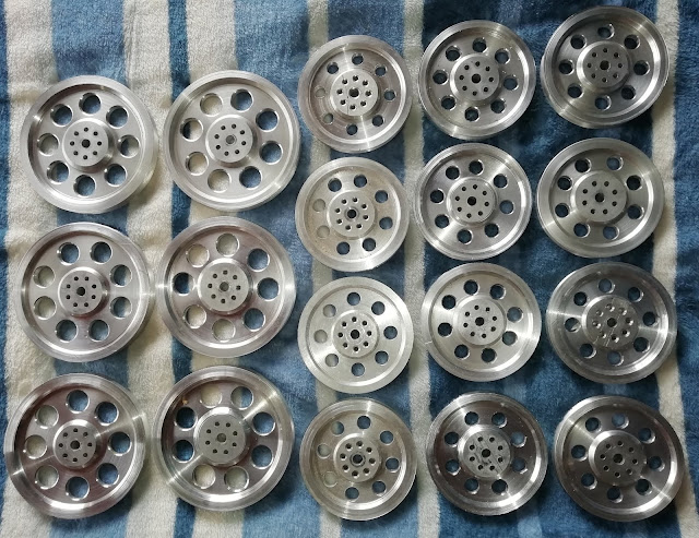
The top end of the main boom is shown in figure 3. This reveals some quite
tricky parabolic shaped plating which I effected using some scrap sheet metal
from an old electric stove and other sources, I felt that a much neater looking
job would result than if I had tried to manipulate standard parts to replicate
the look of the prototype. Also visible in this figure are two rectangular
openings in which will run four 10inch 10 spoke pulleys supporting the four
hoist cables. These pulleys are shown in figure 4. They were laser cut for me
by Steelcut Services of Port Elizabeth from 12mm aluminium sheet. Once again I
must thank Sally Pillay and her team at Steelcut for laser cutting all the
steel and aluminium blanks for parts. The grooves of the pulleys were cut by
myself on a lathe. At this stage I must also thank Roxy Swanepoel at Mr. Screw
of Port Elizabeth for her knowledge and efficiency in supplying some 200 000
fixers.
 |
| Figure 1. 18 foot main boom stored next to Marion 6360 |
 |
| Figure 3. Top end of
main boom showing some purpose cut plates. |
 |
| Figure 4. Four ten
spoke ten inch diameter aluminium hoist pulleys. |
Examining figures 2 and 3 shows that much of the construction was done
using tubular material. It is aluminium tubing of various diameters but a
common wall thickness of 2 mm. The longitudinal members were made from 38 mm
tube. This was all cut into 2.5 inch lengths which had to be accurately sized
in my lathe. These short lengths were then bolted together with a continuous
girder and a continuous strip inside. The reason for this was that a whole
system of joiner cleats had to be bolted on for the lateral and diagonal
bracers to attach and I had to get fingers inside to place nuts. This in itself
was quite tedious but made possible using a fair amount of Prestik ™ to hold
nuts on fingers! The transverse members are 16 mm tube and the diagonal bracers
are 19 mm tube, each section being flattened at each end and bolted with enough
bolts to create a strong join. This is not as neat as the prototype’s welds but
it still looks reasonable. Another criticism is that these sizes of tube are a
bit too large in comparison with a true scale model but then smaller sections
would not have been robust enough. Anyway this sort of thing happens in
Meccano.
 |
| Figure 5. Bridge like bracing structure two thirds way up main boom. |
 |
| Figure 6. Twelve four inch diameter and six five inch diameter aluminium
pulleys. |
Figure 5 shows a detail of a bridge type structure between the two main
side by side units of the main boom. This serves to give added torsional
rigidity to the join between the two side by side units. The unit will also
serve as a support for four 4 inch guide pulleys to keep the hoist cables from
sagging too much and to also act as a damper on oscillations set up in these
due to resonance. The hoist cables are 5.5 inches in diameter so it would not
do to have them vibrating like giant guitar strings! That would do damage to
the boom. Figure 6 shows a dozen of these 4 inch aluminium pulleys. In total
the model will employ 24 of these to do various
things. At the moment 12 are being temporally utilised elsewhere as I
will show. Also visible in figure 6 are six five inch pulleys with other uses.
 |
| Figure 7. One of the minor booms (nine foot) |
At this stage one of the two minor booms which are used to get the
angles right for cables supporting the boom system not to become overstessed
has also been built. It can be seen in figure 7. The mode of construction is
similar to the main boom but now the longitudinal members are 32 mm diameter.
At this stage I will explain one of the most compelling reasons for choosing
the tubular construction mode. Firstly the booms on the prototype are tubular.
In fact if one studies pictures of other draglines it will be seen that this is
virtually universal. Moreover the entire boom system of the prototype was
divided into airtight sections and each was pressurised to seven atmospheres
with nitrogen. These pressures were then continuously monitored and if a drop
in any one was noted the machine was stopped for repair because this meant that
a crack had occurred in a weld. A Meccano girder type boom would not highlight
this feature. Because it was a radical departure from any other technique I had
used I decided to build the booms first.
 |
| Figure 8. Motor/gearbox driver unit for vertical lifting |
 |
| Figure 9. Slide unit and brass M20 receiving end for M20 rod. |
As mentioned earlier the draglines had a method of locomotion which was
different from other classes of shovel and for me it represented some novel
challenges. So this is what I tackled next. The first thing was to build a
pseudohydraulic lifter capable of lifting over 300 kg .This was done using two
window motors ( which I will call 12V motors from now on) driving an M20
threaded rod through two two stage reduction gearboxes. One of these is shown
in figure 8. The threaded rod in turn drives down into a brass fitting machined
from 50 mm stock with an M20 central thread. At the bottom end a 20 mm hole has
been milled sideways and a 20 mm rod passes through this hole into a strong
slidepiece which can slide horizontally on a pair of 20 mm stainless steel rods
journalled into the top of a walking
foot. One of these is shown in figure 9 in a knocked down view. There are four
of these units, each being driven by a motor /gearbox as detailed above. So
eight 12V motors will lift the 1200 kg machine up onto what are essentially
short stilts. Then to do the horizontal slide (of about 9 inches) a set of four
more pseudohydraulic rams, this time based on M12 treaded rods and employing a
single 12V motor each will do the pushing. In figure 10 all four walking feet
are shown, spaced about as far apart as they will be when mounted.
 |
| Figure 10. Walking feet, correct distance apart (overall width 8ft 3 inches) |
In parallel with all this construction has been much part manufacture. Over
9000 plates have been made, the most common one being the 5 by 11 hole , the
total of these being 7000, in gauges 0.6 mm(3000), 1.0 mm gauge (3500) and 2.0
gauge (500).
 |
| Figure 11. 61 inch diameter torroidal mainframe suspended from wheeled wooden gantry crane. |
In figure 11 is shown the very strong 22 hole deep toroidal frame of the
machinery hall. It is 61 inches in diameter and so this is the diameter of the swing
roller rail. As with the previous two excavators I will use one piece 3 mm
gauge flat steel strips for these so as to get a smooth strong rail. The
Toroidal frame was created by bolting 64 eleven by seven hole plates together
offset one hole to give the circle with correct radius and then using these to
position 64 bulkheads plated with 1.0 mm 11 by 5 hole plates. 32 of these
bulkheads go in to a 21 inch diameter ring and32 go in to a 41 inch diameter
ring . A final set of 11 small bulkheads go right in to a 10 inch ring so that
a very strong central hub can be created, the need for which is to support the
tub when the machine goes up on its walking feet. All of these smaller circles
are plated as is the outer surface, the latter with a double layer of 0.6 mm
plates lap joined horizontally and butt joined with flat girder joiner coupons
vertically. As can be seen in figure 11 the spaces between bulkheads have a
lattice of girder bracing. The frame is upside down in the picture so no one
will be walking on this circular surface but the reverse surface will serve as
part of the machinery hall floor and hence is fully plated with a pattern of
plates arranged in concentric rings so that no operating staff will fall down
to the tub, which is a long way down. Structurally the frame consists of a
large number of juxtaposed closed boxes and so is immensely strong. Assembling it
was quite a logistic challenge due to the close spacings of bulkheads.
Consequently some special techniques of assembly had to be worked out.
(Needless to say a lot of Prestik™ was involved, )
It will also be seen in figure 11 that the frame is suspended from a
wooden wheeled gantry crane which was specially built for the purpose. This was
necessary as the frame weighs about 150 kg and is an awkward shape for several
people to get hold of. Flipping it over by hand is frightening to contemplate!
There are two geared winches at the top of the crane, each driven by two 12V
motors.
There are also some pulley blocks seen on either side. This is where the
remainder of the four inch aluminium pulleys mentioned earlier are being
temporarily put to use.
 |
| Figure 12. 71 inch diameter tub. |
In figure12 the matching toroidal
frame called the tub is shown. This has
a similar structure to the mainframe tub but is only one eleven hole plate
deep. A 61 inch diameter ring of plate onto which a similar 3 mm gauge one
piece roller rail will be fixed is visible. The inner ring structure is similar
but now an extra 5 inch wide ring of
bulkheads has been added on the outside. This increases the tub diameter
to 71 inches, making for greater stability and also will serve as space to
affix another 3 mm strip into which 240
eight mm holes will be fixed with about 20 mm of thread facing outward.
This will serve as a 240 tooth ring gear onto which the final drive
pinions of the swing motor/gearboxes will mesh.
Examination of figure 12 shows another feature of the prototype I am
trying to reflect. This is the two colour paint scheme. Accordingly I have
painted some of the plates green so as to match the green boom system. In fact
looking back at the picture of the walking feet shows the same idea on the
visible plates there. There are also some plates which have been painted green
on one side and red on the other for when one colour needs to show outwards and
the other on the inside. The tub was assembled on a special flat table
temporarily put together to ensure that the structure came out as flat as
possible. Once again the crane was useful for lifting the tub off this table
and in fact turning it sideways so that a strong central hub could be
assembled. This hub will anchor the lower end of the rod which bears the full
weight of the tub and also the brass wheels of the roller race.
Finally the tub was lowered onto a 3 inch high wooden platform made of
multiple box units. The reason for this is bound up in the logistics of fitting
the walking feet. Because the model is so massive I cannot lift it up or turn
it sideways to allow each walking foot to be driven on by the screw thread, I
will have to do this without any boxes under the feet at first and then when
feet are tucked up where they should be for digging finally put boxes in place for
them to come down onto. Fortunately this garage has a very high ceiling so I
don’t have a headroom problem at all.
 |
| Figure 13. Shock absorber mechanisms shown rotated through 90 degrees |
At this stage one further mechanism has been completed. This concerns
the two mechanisms shown in figure 13 which will be affixed to the front of the
machinery hall. Each involves four 10 inch ten spoke pulleys. These are
journalled in pairs, one pair in the large fixed unit and the other in the
pendant shaped unit which can swing on the latter unit. The drag cables wind
around these so that when the bucket strikes rock that is too large to drag out
the pendant will swing forwards thus preventing too large a shock going back
and damaging the drag drums. The pendants are weighted so that this does not
happen for virtually no reason. In the case of my model the weight is 4 kg each
unit and it consists of about 1.4 litres of ferrocement which I mix up from cement powder, water and
the fine steel swarf that I have collected over the years from drilling about 2
million 4.2 mm holes. The main machine ballast
will be about eighty sturdy plastic 740 gm mayonnaise bottles filled
with this ferrocement.
The total weight will need to be about 165 kg. (If you are having
difficulty seeing how the described action occurs in the units shown in figure
13 remember that they will be rotated through 90 degrees on the model.)
18th February 2020.
The last two months have been taken up by parts manufacture and the
completion of the main operating machinery. Figure 14 shows representations of
five different types of turned aluminium wheels. There are 108 flanged wheels with 8mm axle bosses. These
are for the main swing roller race (92) and the main support wheels of a five
foot wide servicing gantry crane which runs the length of the machinery hall
and actually comes out an extra foot on an extension rail at the rear. There are
twelve smaller flanged wheels with 4mm axle bosses for the gantry crane cross
traveller. There are 80 bush wheels with 8mm axle bosses, 40mm diameter. These
are for the system of motor/generators (48) and backings to various guide
wheels etc. (32). There are 32 similar bush wheels but with 4mm axle bosses
which will be used for flexible couplings to avoid alignment problems in
various places. Finally there are 12 larger bush wheels, 50mm diameter , to
back the 12 ten inch ten spoke pulleys for the main cable system.
 |
| Fig. 14. Representatives of five different aluminium wheels |
 |
| Fig. 15. One walking foor with operating slider mechanism |
Figure 15 shows a completed walking foot with the slider unit installed
and its driving motor and pseudohydraulic mechanism now working. The large
brass vertical unit has an M20 thread ready to accept the rotating M20 rod
which is one of four which will lift the whole machine onto its walking feet
when it needs to move. All four of these walking feet have now been fitted out
in the same way.
The four matching drive units for the M20 pseudohydraulic actuators are shown in figure
16. Each is powered by two 12V motors driving through two stage reduction
gearing as mentioned before.
 |
| Fig. 16. All four lifting motor/gearbox units (two with M20 brass receiving ends). |
Next the eight swing motor/gearboxes have been built and are shown in
figure 17. I did not have the large 13 tooth final drive pinions for these when
this picture was taken. However I have just taken delivery of these cut from
12mm aluminium stock by Steelcut Services, as shown in figure 18. In figure 18a I have posed two of the pinions on a short piece of 40 by 3 mm strap with M8 bolts acting as the teeth of the main contrate wheel. For the last
two models I cut these by hand using a one hand angle grinder fixed to a table
rather like a butcher uses a band saw. This was very awkward and messy and
lacked the precision of the high resolution laser cutter. My thanks to Sally
Pillay and her team again for a beautiful set of pinions!
 |
| Fig. 17. All eight swing motor/gearbox units. |
These final drive pinions will
mesh with a 250 tooth ring gear created
by setting this number of M8 bolts in a 3mm steel strap installed on the tub
with outward protrusions to act as a large contrate wheel. The previous two
models had four swing mechanisms each but now the moment of inertia is larger
due to the larger mass being swung (1100 kg) and the total length of the BE
4250-W at 26 feet. The dimensions of MI are mass times length squared.
 |
| Fig. 18. All eight aluminium laser-cut final drive swing pinions. |
 |
| Fig. 18a. Two final drive aluminium pinions posed on a short section of ring gear. |
The last of the main actuators are shown in figure 19. These are the
four double sided winding drums, each driven by two 12V motors driving directly
onto 8 inch gears bolted directly to the drum. The latter are fabricated from
two 6 inch face plates at the outsides with a 7 ½ inch face plate at the
centre.(You might notice that the centre units are actually 8 inch light gauge
gears . This was the only error made by Steelcut in 10 years! I didn’t have the
heart to cut them down to 7 ½ inch face plates as they actually mesh with the
12V motor output gears being only one tooth different from the heavy gauge 8
inch gears.). Holding all together are eight M8 rods and nuts. The threads on
the rods have been covered with fish tank plastic tubing to prevent the nylon
covering of the hoist and drag cables being damaged by said thread. A hairdryer
was handy to push the plastic tube onto the rods.
 |
| Fig. 19. Four double-sides winding drums for hoist and drag. |
21st March 2020
I have now mounted the swing roller
race rails above and below, 40 by 3mm steel strap on the tub and 50 by 3mm on
the mainframe. The wider strap on the latter accommodates four 12mm holes
through which the four drag cables will feed from the drag drums to the front
of the machine and the shock absorbers. In figure 20 the upper rail can be seen
as well as two of the 12mm holes.
 |
| Fig. 20. Mainframe with swing roller rail in place and two 12mm holes visible |
In figure 21 the tub toroidal frame
can be seen with its roller rail installed and the 94 wheel roller race in place
thereupon. The roller race consists of another 40 by 3mm steel strap with 94
eight mm holes drilled at a spacing of 50mm between centres. Each wheel runs on
an M8 bolt which is fixed with a locknut into the strap. The 40 by 3mm strap
which will act as a giant contrate wheel has also been prepared with 267 eight
mm holes drilled at 20mm spacing. There will be 267 M8 cap screws fixed into
these holes with 30mm of thread pointing outwards to act as the teeth of the
contrate wheel. This will be fixed to the tub outside the roller rail. This is
contrary to the prototype which had a planar ring gear inside the roller rail.
The reason for the change is that I want the swing gearboxes to be accessible
without having to dismantle the whole model in case any of them needed
servicing. (I do not have any 4 inch high servicemen who can get inside the
model!)
 |
| Fig. 21. Tub with 94 wheel roller race sitting on roller rail |
Figure 22 shows one of the swing
motor/gearbox units with the 13 tooth aluminium final drive gear installed.
While testing these units I was mindful of the fact that if a finger should get
into the rotating gear it would probably be sheared of at the joint since the
torque transmitted here is huge.
 |
| Fig. 22: One of eight swing motor/stroke gearbox units with aluminium final drive pinion |
 |
| Fig. 23: Four double winding drums mounted on top side of mainframe |
The two double winding drums for
hoist and the two for drag have now also been installed on the upper surface of
the mainframe which is part of the hall floorpan. These can be seen in figure
23. These units were installed with the mainframe held sideways in the wooden
gantry crane. The reason I have installed them at this stage is that that they
are a long way in from the edge and one’s arms are not long enough to do the
job after the mainframe has been placed on the tub. The attachment was a tricky
job as the units are rectangular while the floorpan is radial. A series of
girder lugs was built into the floorpan and these were used in an opportunistic
way, with several flat girders bent with a bend transverse to the said flat
girder to connect the disparate types of structure. Also seen in figure 23 is a
14 inch face plate in 2mm gauge which has been fixed to the centre of the
circular floor. This is bolted to a very strong central hub which was assembled
in the central space in the frame. This will bear the weight of the tub when
the machine is ready to walk, through the M12 rod which supports the tub. This
14 inch face plate is actually the dropout from getting a plate with a 14 inch
hole cut in it for the minor roller race track of my Krupp 288 model. I thought
it would come in handy one day!
Finally during the last month or so
I have built the bucket, using pictures I have to get the details as correct as
possible. There seem to be some differences in detail of various buckets used
on the machine. I know that there were three buckets which were used in
rotation as repairs to any one had to be made every seven months or so due to
the highly stressful job it was doing causing inevitable damage. Qualified
welders were a permanent part of the machine team.
There is a lot of detail in the
bucket so I have included several pictures, namely figures 24, 25, 26, 27 and
28. Figure 24 is a side view while 25 is a view from the front and shows the
six large digging chisels. Figure 26 is an oblique view while 27 is a close up of the way the main hoist chains
are attached using an M8 bolt through two plate thicknesses one inch apart so
that bolts do not get twisted upward by the weight of the unit. Figure 28 is a
view of the rear and shows some heavy strapping effected using three
thicknesses of flat girder to mimic the prototype. These straps go underneath
the unit as well. These all go to make the bucket very strong. I think it could
be filled with a scale load of 35kg. The colouring of the bucket needs some
explanation .While these buckets are working the inside, bottom and some lower
and frontal surfaces become polished to a newly sanded look by the material
being handled. Accordingly I have coloured these areas silver (actually cold
galvanising). The remaining surfaces are a matt black. It will also be seen
that the four main chains have been attached. Many years ago I planned to build
a swing for my children but then changed jobs and found myself in a new town
building a home for my family. Swing never got built and I’m still working on
the home 40 years later! The chain I bought back then proved to be exactly the
size I needed here.
 |
| Fig. 24: Side view of bucket |
 |
| Fig. 25: Front view of bucket showing drag chains |
 |
| Fig. 26: Oblique view of bucket |
 |
| Fig. 27: Attachment of hoist cables |
 |
| Fig. 28: Rear view showing reinforcing straps |
Figure 29 shows a more detailed shot
of the very strong central hub which has been assembled and which supports the
14 inch diameter plate which has in turn been reinforced with a 5 by 15 hole
2mm gauge plate bent down the middle to form a girder.
 |
| Fig. 29: Strong central hub with 14 inch face plate |
Some more work has been done on the winding
drums in figure30. This shows protective cowlings mounted over the 8 inch drive
gears. Also over four of them observation platforms have been installed to
allow engineers a vantage point from which to observe the revolving drums to
check for any possible malfunction. Short sections of ladder will connect these
to a network of staff gangways to be installed. Also seen in these pictures are
sixteen “cosmetic” representations of the sixteen 1000 horsepower motors which drove the winding drums on the
prototype.
 |
| Fig. 30: Some cosmetic work on winding drums and correct length cables installed |
At this stage all eight individual drums have
had sufficient cable installed to enable the machine to send a bucket down 10
feet, which is the scaled equivalent of the 185 foot depth of dig on the
prototype. This is 13 metres on the drag drums and 18 metres on hoist drums.
Braided steel cable of diameter 2mm with nylon covering has been used. I am
confident that the drums and cables are sufficiently strong to drag and hoist a
scaled load of about 35 kg but of course I will not be doing that as my
gearboxes are all open and would not be able to handle grit getting into them.
Finally I have wheeled the mainframe
over to the tub and lowered it so that it now rides on the 94 wheel roller
race. The M12 rod has also been manoeuvred into position and the nuts keeping
the two units together when the tub is lifted off the ground have been fitted. This
work is shown in figure 31.
 |
| Fig. 31: Upper toroidal frame sitting on tub with roller ring between |
The future order of building will be:
- Install
the eight swing Units together with the 267 tooth swing contrate gear.
- Build
the toroidal mainframe out to a rectangular floorpan, 6 inches in the
front and sides and 30 inches at the rear.
- Mount
the four lifting units to the outside of the floorpan structure.
- Mount
the walking feet.
- build
the machinery hall out another 6 inches on either side.
- Mount
the frontal shock absorber units.
- Build
the gantry.
- Install
entire boom system (already built) and hoist into final position being
careful to have about 250 kg ballast in place at machine rear. To do the
hoist I will remove the two winches from the wooden crane and install
these temporarily on the machine gantry.
- Install
system of motor generators on rear of hall floor.
- Build
cabin enclosure, slowly reducing ballast to 160 kg.
The 267 tooth contrate wheel has now been
assembled. The teeth are M8 countersunk CAP screws with 30 mm thread protruding
out from a one piece strap of steel, 40mm by 3mm.The eight swing motor/gearbox
units have also been installed and wired up. Figure 32 shows these
developments. Figure 33 shows the top of the toroidal frame loaded with some
boxes containing 300 kg new plates to
provide some additional weight for testing the swing units.
 |
| Fig. 32. The swing motor/gearboxes on one side. Also the contrate wheel in place. |
 |
| Fig. 33. Boxes containing an extra 300kg of parts to test swing. |
The next step is to develop the 61 inch
circular frame out to a six foot square
frame . The connection between frames will be 64 bulkheads bolted to the outer
girders on the toroidal frame coinciding with the 64 inner bulkheads of said
frame. These vary in width from 5 inches to 20 inches and are all fully plated
with 1mm gauge 11 by 5 hole plates using a high bolt density as they need to be
very strong. The four lifter units will be attached to the outsides of the
square frame and hence very large force and very large moment will be exerted.
The bulkheads are all 22 holes deep except for those which are 11 holes deep,
necessary to make room for the swing units. Some very strong lower chords will
need to be installed in order to even out the distribution of stress.
 |
| Fig. 34. 64 bulkheads joining toroidal frame to outer square frame. |
 |
| Fig. 35. View down one side of square being created. |
Figure 34 shows the 64 bulkheads from above
while figure 35 shows the straight edge formed by bulkheads on one side. At
this stage the four outer edges of the frame have also been assembled and one
is shown in figure 36. The sides are 72 ½ inches while the front and back are
73 ½ inches. The extra inch was added to give clearance for the swing drives.
 |
| Fig. 36. One of the four sides fully assembled |
The next task is to attach the four sides of
the square. This will need some fettling and adjustment. I have some 110 degree
and some 135 degree obtuse girders to start with. These angles can be adjusted
in a vice to suit. Some extra slippage will also be necessary.
So far so good in figure 37 which shows the
sides in place, bolted at the corners and the midpoints for now.
 |
| Fig. 37. All four sides mounted and reading for joining to bulkheads. |
July 1st 2020
The view shown in figure 38 looks very similar
to that shown in figure 37, except for an increase in the number of bolt heads
visible. This is because figure 38 shows the machinery hall frame with all 64
of the connecting bulkheads between the toroidal frame and the square frame now
fully bolted up to create a very strong structure .From figure 37 to figure 38
there are an additional 2000 bolts and much obtuse girder and flat girder
material. Since virtually every bulkhead connects at a different angle and a
different distance this job required much fettling by way of obtuse angles
adjusted slightly in a vice, many 4.2mm holes reamed out to 6mm for extra
slippage, some flat girders with an extra 1/16 inch between the hole lines and
some strips for fine adjustment. |
Fig. 38: All 64 bulkheads between toroidal frame and square frame connected
|
With the floor mainframe completed I could
start attaching fittings which go onto the structure. Figure 39 shows the
pseudohydraulic lifter motor/gearboxes fitted to the right side of the machine.
Figures 40 and 41 are close ups of each of these. The attachment has to be
immensely strong since each unit experiences an upthrust of nearly 300 kg when
the machine goes into walking mode. Accordingly, the lower chord of the
mainframe has been reinforced with 2mm gauge plates so as to spread the load
out to as large an area as possible and not let it impinge on the toroidal
frame as a point load. Visible in figure 40 are two specially bent 2mm plates
which will connect each lifter to the lower frame chord.
Also visible in the above figures are very
strong 7 inch high posts which will be connected to an anchor point on the
outer floor, which itself will be plated in 1mm plate for a very strong floor.
This will reduce the effect of the moment of force exerted by the lifter unit
on the side of the square frame.
A similar plate structure has been built onto
the lower side of the mainframe to help distribute the force exerted there by
the lifter mechanism.
 |
Fig. 39: Lifter motor/gearbox units on right side of machine
|
 |
Fig. 40: Right rear lifter
|
 |
Fig. 41: Right front lifter
|
At the front face of the square frame the two
shock absorber units for the drag cables have been fitted. These are shown in
figures 42 and 43. The eight ten inch ten spoke wheels have been posed in place
too.
 |
Fig. 42: Drag cable shock absorber
|
 |
Fig. 43: Another view
|
Figure 44 shows some work on the right front
face to install the supports for the boom system (green plate.) The heavy gauge
plates in red are actually inside the hall and are supports for the right front
strut of the gantry. These have 10mm
holes for an M10 bolt. The boom system will be supported by m12 bolts.
 |
Fig. 44: Support for boom system and for front right gantry member
|
Figure 45 shows a view from the rear. There are
nine vertical girders bolted onto this face to receive the nine bulkheads which
extend over two feet to create a large box at the rear of which will be placed
about 165kg of counterbalance ballast in the form of 80 bottles of ferrocement
as explained earlier.
 |
Fig, 45: Rear view where large box will be installed, with ballast at the rear.
|
Finally, by way of an advance experiment, I
have built the roof truss and a floor truss for the mezzanine floor which
supports the air filtration plant for cooling air. These are shown in figure
46.
 |
Fig, 46: Roof truss and combination roof and floor truss for air filtration units in mezzanine floor
|
August 22nd 2020
At last the model is showing some completed
outer surfaces and features. The lower front end is now complete with its
stairs and walkways for staff to get onto the machine and to observe the eight
large pulleys of the shock absorber units checking for any malfunction. Note
that all this work is in green in accordance with my version of a two colour
scheme. These can be seen in figures 47, 48 and 49.
 |
Fig. 47: View of front end showing access stairs and walkways
|
Figure 47 focuses on the left side of the
machine showing the path from the ground up to a walkway which runs along the
entire machine front and then on up to an observation platform around the top
of the front left lifting unit.
 |
Fig. 48: Close-up of strong supports for boom system and front end of gantry
|
Figure 48 is a similar shot but taken from
further back and shows also the M12 bolt support for the left side of the main
boom, the M12 bolt support for the left minor boom and in red (because it is
actually the machinery hall) the M10 bolt support for the left front gantry
stanchion. 
 |
Fig. 49: Shock absorber units
|
Figure 49 focuses on the shock absorber units.
The fittings made of aluminium tube bent to shape are motion limiters to
prevent the pendants from swinging out too far. On the prototype these do not
feature in early photographs so they were a retrofit. Also obvious from a
comparison of early and later photographs is the retrofit of extra bracing of
the front, which is reflected in my model in the section of strut using 135
degree obtuse girders which goes across the whole width. Engineers must have
found that front was taking a pounding from the drag action.
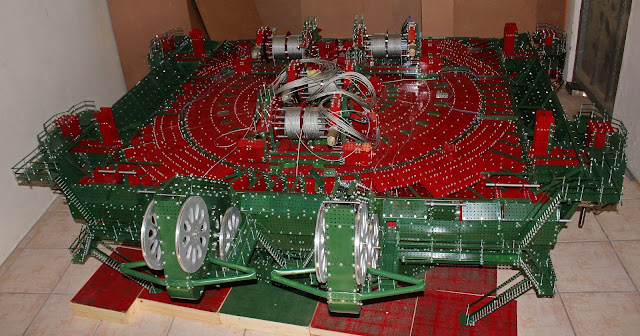 |
Fig. 50: Overall aerial view
|
Figure 50 is an aerial view of the main body so
far. All four of the lifter units have been fitted and some exterior cowling to
these has been built. Observation platforms are also now showing on these. The
final full width of the hall building is now showing in figure 50. The main supporting
structure is the same width as the square mainframe (all in red) but sideways
extensions to this are seen on either side (in green). These will not go the
whole length of the hall. These form two “lugs”, one on either side. Making
matters more complicated is the fact that the two lugs are not the same height!
I think this might have had something to do with a system of large air ducts
carrying cooling air down from a filtration plant on a second, mezzanine floor.
Also visible in figure 50 is some more floor
plating . This has been done in 1.0mm gauge plate and is very strong. This will
help spread the large force exerted by the lifter unit when the machine gets
ready to walk. Similar plating has been done on the underside of the body for
the same reason. Here the force will be outward.
 |
Fig. 51: Left side valence
|
Figure 51 shows an angled valence which forms
the support to the above mentioned lugs. This is relatively lightly built as it
only has to support about 10kg. The main weight of the machinery hall walls and
roof, as well as the air filtration plant (about 200kg) will be supported by 12
strong vertical stanchions rising off the floor. Another 12 lighter stanchions
will support rails for a servicing crane which runs the length of the machine
and actually out the back. Also visible in figure 51 is the M20 spindle of a
lifting unit.
 |
| Fig. 52: Close up view of several systems |
|
|
Several different systems are represented in
figure 52. Firstly the 13 tooth drive pinions of two of the eight swing drives
are obvious. Then part of the 267 tooth contrate wheel formed from M8 bolts
protruding outwards from a 3mm thick steel belt is visible. Measures to
withstand the enormous moment exerted by the lifters are represented by several
things in this figure. Straps of 2mm plate connect the bottom of the lifter to
a heavily made lower chord of the mainframe (also employing 2mm plate). At the
centre of this chord is a section of 3mm girder necessary to get past the four
swing units on this side. Finally some of the 94 aluminium flanged wheels of
the roller race ride between upper and lower rings of 3mm rail.
 |
Fig. 53: Rear view of side valence
|
Figure 53 shows some coachwork needed to
terminate the angled valence at the rear. The back face of the machine shows in
red because there is still a large box to be built at the rear, extending about
30 inches back and housing 165 kg of counterbalance ballast in the form of 80
bottles filled with ferrocement as explained earlier.
I am grateful to Mrs. Lynette Rudman for her
skilful camera work in figures 47 to 53 inclusive.
October 23rd 2020
Considerable work has been done during the last
few months, some of it cosmetic and some decidedly not so, being heavily built
members of one sort or another. Looking at figure 54, an overall aerial view,
the most evident new work is the main gantry which can be described as two
A-frames side by side with two joining crossbars between the front two members
and then four angled braces between said crossbars. The front struts are each
bolted to the mainframe with M10 bolts and nuts going into angle brackets made
from 2mm material. These struts will be in compression when the main boom is
fitted. The rear struts are bolted into some bent 2mm plates going deep down
into the mainframe at the rear. These will support great tension.
 |
Fig. 54: Overall view at present
|
The front struts are box girders formed by
laying 9 by 5 hole 0.6mm lap joined
plates between angle girders in the four corners. Additional strength is
provided by having a flat girder in each corner, butt joined wit lap joined
four hole long flat girder coupons. For additional rigidity lateral bulkheads
are sited every 16 inches along the inside. The two rear struts as well as the
two cross members are similarly constructed but are now only seven holes wide,
using 11 by 7 hole 0.6mm plates.
The front and rear struts are joined with at
the top with more M10 bolts and nuts. Looking at a side view of the gantry in
figure 55 one can see that the gantry is flat topped at this stage. It will
eventually be extended upwards to a point
by means of some 2mm plates. At the apex will be some 4 inch aluminium
V-pulleys which will be part of the boom lifting mechanism. In fact there are
already four such pulleys running in strong journals at the top of the gantry
crossbar, as seen in figure 54. The boom support system consisting of 12 M5
threaded rods will also be anchored to the 2mm plate construction just
described.
 |
Fig. 55: Note flat topped gantry
|
Moving to the rear figure 56 shows the tapered
side of the rear box which has now been completed. This will house the
counterbalance ballast. The lower floor of the box is made fro 1.0mm plate, as
are the nine bulkheads extending rearwards. The upper floor, which forms part
of the whole machinery hall floor is made of 0.6mm plates as it does need to be
as strong as the lower floor. Figures 57 and 58 show two views of the motor
generator park which is bolted to this upper floor. There are six high voltage
motors powered by the incoming 13800 volt three phase power driving four
generators each. The latter provide low voltage DC power for all the machine’s
many motors. The torque characteristics of DC motors are better than AC motors
and also 13800 volts is too high for safety. Total maximum power is 62000 horse
power so one can deduce that each HV motor is very powerful. I presume some
power is put through transformers to provide
low voltage AC for lighting, the operator’s kettle for coffee etc.
 |
Fig. 56: Tapering box-like extension to the rear
|
The M-G park employs some recycled material in
the form of plate cut from old coffee tins and the round bodies of the HV
motors from the same source. The ersatz rotors of the generators are the tops
of Rustoleum spray paint cans cut and pushed together. The ersatz stators are
stacked washers. To avoid alignment problems, the common shaft to each unit is
journalled in only four points and also employs a flexible drive unit on either
side of the motor. Each of these consists of two aluminium 8 hole bush wheels
and a diaphragm of 3mm insertion rubber. These bush wheels are for the 4mm rod
system while the bush wheels which form the ersatz bearing boxes of the
generators are for the 8mm axle system, so 4mm axles actually don’t touch. Each
unit spins freely and I would have liked to have them turning but I have been
unable to source enough small Meccano motors for this. Also Visible in figures
57 and 58 is a comprehensive system of walkways and guard rails to allow the
electricians to walk safely in M-G park.
 |
Fig. 57: Motor, generator park, showing 6 MG units
|
 |
Fig. 58: M-G park again. Note walkways with handrails.
|
Figure 59 shows a view from the rear in which
some of the eight holes through which the ballast will be fed are visible. Also
visible is the lower outer corner plating which employs some 0.6mm plate bent
to a tight radius. The 4250-W had these rounded corners in many places.
 |
Fig. 59: View from rear showing some holes to place counterbalance ferro-cement.
|
Figure 60 shows another bit of successful
recycling .This is a set of nine cooling fans from old scrapped computers which
were kindly donated to me by Mr. Pieter Burger, our local recycling guy in
town. I intend mounting these around the walls of the machinery hall , imitating
the extractor fans on the prototype.
These are just about the right size and being 12V I will be able to have them
spinning!
 |
Fig. 60: Nine cooling/extractor fans from scrapped PCs (compliments of Mr Pieter Burger!)
|
|
Figure 61 shows all 12 of the main vertical
supports to roofs and air filtration plant floor, the latter being situated
above M-G park. These are all channel girders consisting of two girders and a
three hole wide plate each in cross section. The longer six go right up to the
top of the machine to support the roof of the air filtration plant.
 |
Fig. 61: All twelve main upright support stanchions for machinery hall
|
Figure 62 shows one roof truss, one mezzanine floor truss and two combination roof/floor trusses. The latter units will support the large air filtration plant in a mezzanine floor to the rear of the maching.
 |
Fig. 62: One roof truss, one mezzanine floor truss and two combination roof/floor trusses.
|
Once again I express my thanks to Lynette
Rudman for her skilful photography in figures 54 to59 inclusive.
December 10th
I have now started the large machinery hall
enclosure. There will be about 2500 plates in this structure, mainly 11 by 5
hole in the 0.6mm gauge, with most being drilled around the perimeter only. The
reason for this is that I wanted to avoid an appearance of excessive “
busy-ness” in such large surfaces. In places where I need to put in some bolts
through the middle of a series of plates I have used more standard looking full
face drilled plates in line with the familiar flat plate of Meccano.
 |
Fig. 63: Front view showing guide pulleys as well as roof, built back to start of upper floor
|
Fig. 64: Close up of guide pulley support structure
Figure 63 shows a view of the hall front as
well as the roof decking as far back to where the second or mezzanine floor
supporting the air filtration plant will start. At the centre of the upper edge
with the roof is a structure which houses four guide pulleys to get the four
hoist cables safely out the machine hall. Some careful scale drawings were made
to ensure that the cables did not touch the roof trusses or anything else.
Remember that these cables come off winding drums set one behind the other. Figure
64 is a close up of this structure, showing the four 5 inch aluminium V
pulleys. Examination of figure 63 also clearly shows the curved edge between
roof and front wall. This was effected using 11 by 5 hole plates in 0.6mm gauge
with 8 holes reamed to 6mm and curved in the vice. Although there are no
girders in these corners the tight curve on the said plates gives a lot of
rigidity.
|
Fig. 65: Corner showing three curved edges coming together and short piece of rain gutter.
|
Figure 65 shows a corner where three curved
edges come together. Also visible at this corner is a section of rainwater
gutter made by putting two longitudinal bends into a 3 by 11 hole flexible
plate (actually recycled from old coffee tins, a brand which does not come in
corrugated tins!) The downpipes will be 8mm wooden dowels painted red.
The 12 main stanchions which bear the weight of
the roof and also brace the walls are being installed as I move from front to
rear. The rear 6 of these go right up to the roof of the second floor and also
support the floor trusses of this structure. The second floor will house the air
filtration plant. I have not been able to find any details on the latter. There
are a number of walkthrough videos of the interior of the machine but none go
up to the second floor. Also most videos I’ve seen are very shaky and don’t
seem to have any plan to them.. Hence I’ve had to make some guesses at the
layout of the air filtration plant. One thing that mystified me for some time
has been clarified by a very sad picture of the 4250-W taken just before it was
scrapped and a lot of the plating had been removed. I always wondered why the
two side “lugs” on the hall were asymmetric, rising to different heights. In
this picture there is a clear view of a large air duct at the top of the higher
of the two lugs. The purpose was probably to bring cooling air forward to the
front of the machine. In figure 66 I show an S-bend followed by a left turn in
the air duct to be installed. I have painted the air duct silver to imitate the
galvanised sheet metal of the prototype.
 |
Fig. 66: S-bend followed by left hand turn in air duct
|
Figure 67 shows this same fabrication installed,
revealing the need for its strange shape .The rear section of the duct will link up to two large impellor
pumps while the side section has two outlets which play over the winding drum
area. On the other side of the filtration plant two similar pumps will cool the
M-G park. Figure 68 shows this same area being plated over, and the rather
peculiar shape of the side of the hall is now revealed.
 |
Fig. 67: Air duct installed
|
 |
Fig. 68: Same as Fig. 67 now with some body plating
|
Figure 69 is a shot taken into the rear of the
hall. It shows the other side of the air duct as well as the roof trusses of
the main roof. Paired with each main stanchion there can be seen a second
smaller one which holds up a rail for the 5 foot wide service gantry crane.
Part of the installed rail can also be seen. The clearance between the top of
the rail and the bottom of the roof trusses is 5 inches. I have got the design
height of the crane down to 4.5 inches so clearances are tight but workable.
Note also that the clearance with the air duct is similarly tight. Throughout
the model small clearances between large units has been a recurring theme,
making the BE 4250-W the most challenging build of the three mega models.
 |
Fig. 69: View into hall, showing air duct, gantry crane rail and main and auxilliary stanchions
|


